
When you need to perform installation and maintenance of gate, check, or butterfly valves, standard operating procedures contain instructions for technical work and safety protocols that everyone should follow. In large industrial units where maintenance performs on an annual shutdown basis, strict guidelines are followed. There are three main types of maintenance as the following:
· Preventive Maintenance
· Predictive Maintenance
· Breakdown or Shutdown Maintenance
We usually perform preventive maintenance of valves while they are in operation. It usually comprises a set of checklists to be filled considering valve conditions. Predictive maintenance depends on field rounds and operation parameters. We analyze unusual numbers and predict valve conditions and, in worse cases, breakdown. We perform corruption or shutdown maintenance when a part of the valve break or the whole process shut down for maintenance. Below are procedures for the maintenance and installation of popular types of valves.
Resilient Seated Butterfly Valves
Installation Recommendations
Valve Ratings
Valve pressure ratings are indications on the nameplate attached to each valve. Check valve operating pressure and temperature before proceeding to installation.
Valve Seat Position
Usually, butterfly valves are bi-directional, and installation is not dependent on seat orientation. However, we should check the condition of the seat before installation.
Disc Clearances
Before we install a valve in a pipeline, we much check that the ID of the valve and pipe are the same. Therefore, the disc of the valve can rotate freely without damage. Damage to the disc edge can severely affect valve performance. Flange and pipe should have compatible schedules.
Opening Rotation
We must check disc rotation before installation. Disc rotation is key for proper and safe operation in a process.
Installation Position
To avoid any damage to the disc and seat during the installation, we should partially open the valve disc but should not extend beyond the valve liner face. In this position, shaft and disc weights distribute evenly, minimizing seat wear and providing a stable valve position. We should also remove any foreign matter that may cause wear.
Valve and Flange Preparation
We should remove any dirt, grit, dents, and surface irregularities to avoid external leakage and flange sealing disruption. We should also inspect the valve disc sealing surface and seat for any material that will adversely affect valve operation.
Installation Tools
Usually, we require the following tools for the installation of valves at the surface and height:
· Screw Wrench
· Levelling device
· Torqueing Wrench
· Chain Block
Required Bolting
For checking relative bolting requirements, one should consult the process and instrumentation diagram. We can find every information related to flanges, gasket, bolting, and bolt tightening values on this diagram.
Unpacking and Storage Instructions
· Check packing list to verify size and material of construction
· Inspect valve thoroughly to check if there was any damage during shipment
· While lifting the valve avoid damage to flange faces, disc, and seat
· For storing valve avoid harsh environment conditions
· Store valve in almost close position to protect sealing edge and seat
· Keep valve away from dirt, debris, and corrosive material
· Keep valve in a dry area with flanges protected and on a suitable skid or pallet
· Keep the valve in a cool position away from direct sunlight
Pre-Installation Procedure
· Make sure pipeline is isolated by checking tags and relative area supervisor
· Remove any protective flange covers from the valve
· Inspect pipe fluid way, flange face, seat, sealing surface, pipe edges and remove dirt
· If there is any actuator, we should assemble it with valve before installation
· Check tags to ensure pressure rating and materials compatibility to the application
· To check the direction of installation, always follow the process & instrumentation diagram
· Check bolts, nuts, and studs for proper size and threads
Valve Installation Procedure
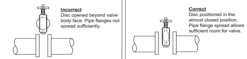
1. Position connecting pipe flanges inline to ensure proper alignment before valve installation
2. Spread pipes flanges apart to allow them to locate between flanges without touching them, as figure 1 shows below:
For Wafer Type Butterfly Valve
· Place valve between flanges
· Loosely install two upper and lower bolts
· Install all the remaining bolts shift the valve as necessary to permit bolts through the body of the valve and flange
· Hand Tight as necessary
For Lug Type Butterfly Valve
· Place valve between flanges
· Install all bots between valve and mating flanges
· Hand Tight the bolts as necessary
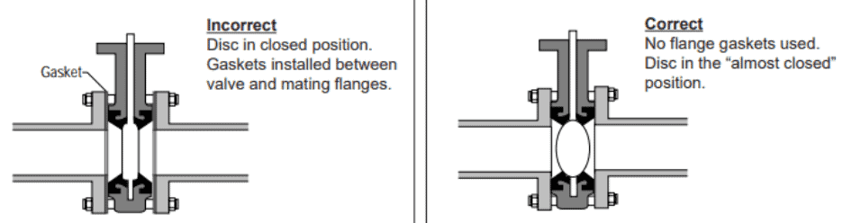
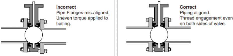
3. Before completing the tightening of bolts, the valves must be aligned and carefully opened and closed to ensure unobstructed disc movement, as shown in figure 2 below:
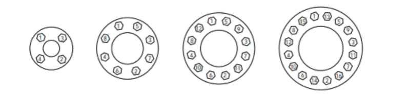
4. Use the star method to ensure even tightening of bolts as shown in the figure3 below:
5. If there is any actuator, its air hoses or electricity connection to be provided as per manufacturer instruction
6. Check if there is any bidding in the valve by full opening and closing the valve
7. Check actuator travel stop settings for disc alignment
8. Valve is ready for operation
Maintenance Recommendations
Safety Precautions
Before maintaining or removing the butterfly valve from the line or loosening any bolts, it is essential to verify the following conditions:
· Ensure line is depressurized and drained
· Check isolations tags and consult with relative area operator or supervisor
· Ensure all required personal protective equipment is available
· Be sure of pipeline media and follow all safety protocols in case of toxic or flammable material
· Never remove the operator, handle, or any part while the line is still under pressure
· Never remove the valve without an operator already attached to it
· Always ensure the disc is in the closed position before removing the valve
· Follow all recommendations given in job safety analysis or risk assessment
· Take a valid permit before removing the valve
· Ensure everyone in your crew is aware of hazards related to removing the valve
· Use chain block or crane if the valve is heavy or at height
· Give proper toolbox talk before removing or maintaining the valve
General or Preventive Maintenance
Following are general or preventive maintenance guidelines that everyone must follow for a butterfly valve.
· To check operability, operate the valve from a fully open position to a fully closed position
· Inspect flange and bolting to check to loosen and correct as needed
· Observe valve and surroundings for any previous or new leakage at flange faces or shaft connections
· Check Piping and wiring to actuators for leakage and damage respectively and maintain as needed
Butterfly Valve Disassembly
· position the valve horizontally with the disc in the closed position
· Use a hammer and punch to loosen taper pins from the valve disc
· After removing pins, extract the shaft using a twisting motion
· Remove valve disc from the valve body, making sure seat and disc do not damage
· Remove cartridge seat by applying pressure on one face pushing the heart through the body
· Remove shaft bushings from the body
· Inspect all parts of valves thoroughly
· Utilize mechanical machinery for repairing valve
· Replace bushings and seat if damaged
Butterfly Valve Assembly
· Completely clean all parts and inspect components for any defects before assembly
· Do not let the use of any dirty, gritty, or damaged surface
· Apply small amounts of silicone grease to the inside surface of the body, including all shaft holes
· Insert shaft bushings into the body without damaging the bore
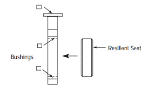
· While installing the seat in the valve body, make sure shaft holes in the seat line up with the holes in the valve body as shown in Figure 5
· Completely coat seat inside surface with silicone grease
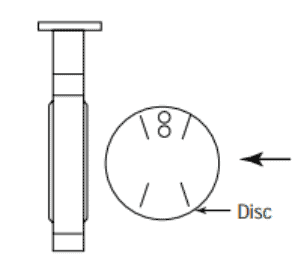
· Carefully install disc in a fully open position, i.e., 90° to valve body as shown in Figure 6
· Insert shaft through the body and disc using a twisting motion to align the keyway with the disc
· Insert taper pins into the disc and set with two to three hammer blows
· If the valve is a dead-end service design insert set screws through the body into the seat.
Ratchet Handle Mounting Procedure
· As for all maintenance procedures, position the disc in a closed position
· Install Ratchet plate using machine bolts, nuts, and lock washers but do not tight
· Tap the drive key in the shaft and ensure it is fully seated in the keyway
· Install the handle as it is parallel to the face of the disc
· Tighten the set screw in the handle against the key
· Flush the ratchet plate
· Engage locking lever with ratchet plate
· Using the handle, adjust the position of the ratchet plate until the disc face is parallel with the ratchet face
· Tighten the fasteners of the ratchet plate
Manual Gear Mounting Procedure
· position the disc in a closed position
· Install the drive key in the shaft
· Tap the key to ensure it is fully seated
· Rotate gear shaft in a full clockwise position
· Align the keyways in the bore of the gearbox with the key in the shaft
· Slide the gearbox onto the shaft
· Fasten the gearbox to the mounting bracket with appropriate machine bolts and lock washers
· Align the gearbox slightly to align mounting holes in the gear with the plate
· Adjust stops of the gearbox as parallel to the face of the valve in the closed position and perpendicular in the open position
Remote Actuator Mounting Procedure
· Place the valve in a closed position
· Install the actuator-mounting bracket on the valve body with actuator mounting holes facing upward. Fasten the bracket securely in place with bolts, nuts, and lock washers
· Install the drive key in the keyway of the shaft
· Tap the key to ensure it is fully seated
· Install the drive coupling on the shaft by lining up the proper keyway in the collar with the key in the shaft
· Rotate the actuator shaft to a clockwise position. Align the drive coupling with the actuator shaft and install the actuator on the mounting bracket
· Fasten the actuator to the mounting bracket with appropriate machine bolts and lock washers. It may be necessary to rotate the actuator shaft to align mounting holes in the actuator with the mounting bracket.
· Adjust the stops in the actuator to position the face of the disc parallel to the face body when fully closed and perpendicular when fully opened position.
Conclusion
Whichever is the valve type, we have to do all three types of maintenance, i.e., preventive, predictive, and breakdown or shutdown maintenance? Therefore, having an excellent technical crew with the right hands-on practice is always better for valves’ proper maintenance.